Magnetic field in the air gap of DC electric motor
Magnetic field distribution in the air gap of a DC motor, and a comparison of the pole leakage factor under two different modeling formulations.
Engineering Problem
How can the pole leakage factor in the air gap of a DC motor be computed?
Answer
Solve a magnetostatic problem, read the leakage flux and total flux from the field plot, and their ratio gives the pole leakage factor.
Typical Applications
- DC motor air gap
- Commutator motors
- Motor pole assemblies
Simulation Problem
- Problem Type
- Linear plane-parallel DC Magnetics
- Geometry
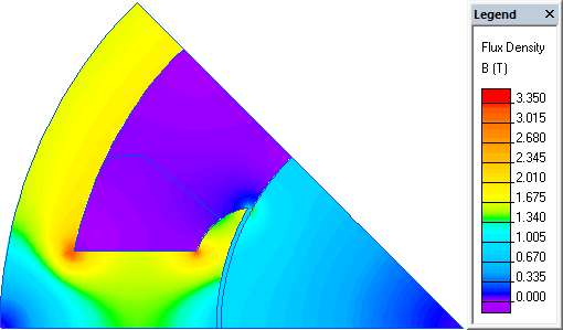
- The air region is defined by contour abcdefg. Dimensions: ab = 2 mm, ag = 32°, cd = 68 mm, bc = 45°, de = 30°, ef = 55 mm. The rest of the motor is represented through boundary conditions.
- Given
- Rotor and stator steel relative permeability μ = 1000
- Air relative permeability μ = 1
- Coil current density j = 1 A/mm²
- Motor power 45 kW
- Task
- Plot the field lines in the non-magnetic region of the DC motor, and compute the pole leakage factor under two formulations: first, with the coil defined by its current distribution and steel given a finite permeability; second, a simplified formulation with the steel treated as having infinite permeability and the coil represented by a current sheet.
- Solution
Real motor model: using symmetry, Ht = 0 is set on line Od and A = 0 on line Oa.
Simplified model (test rig): Ht = 0 on the steel surface (lines defga and bc) and on the axis of symmetry Od; A = 0 on line Oa.
- Results
Real model: leakage flux 1.11 mWb, total flux 52.93 mWb, ratio 0.021.
Simplified model (test rig): leakage flux 3.39 mWb, total flux 78.87 mWb, ratio 0.043.