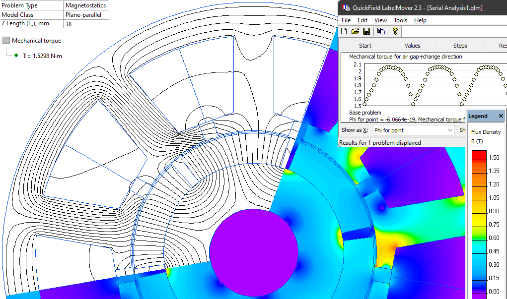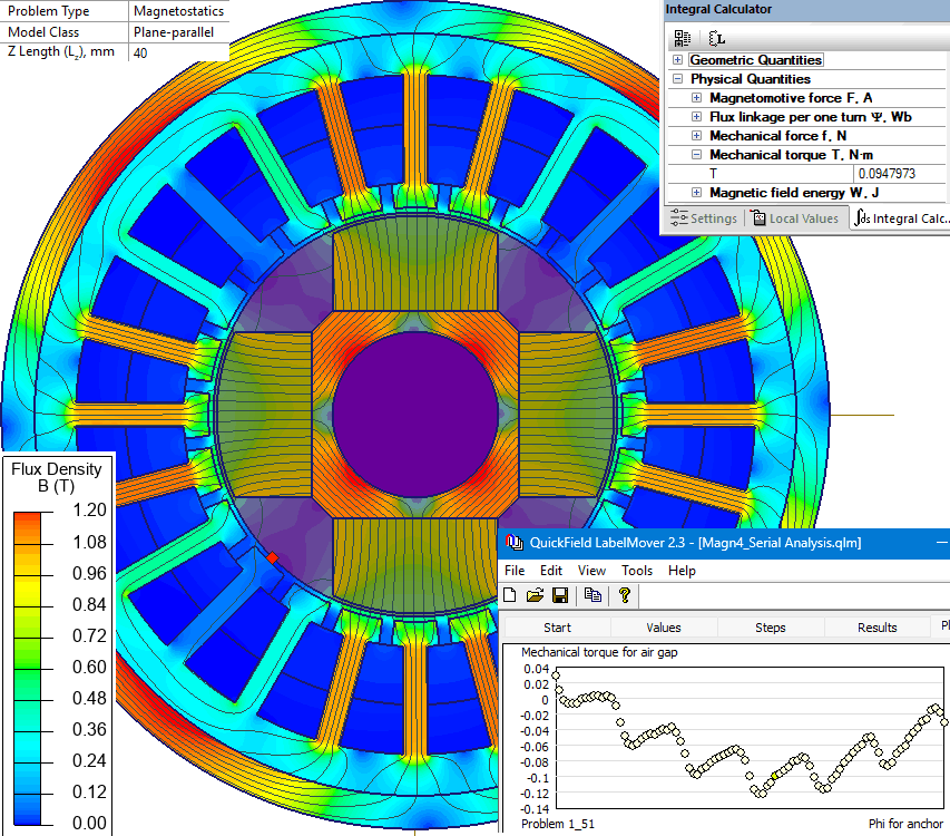
BLDC motor slots skewing
Cogging torque and no-load back EMF of a BLDC motor with skewed stator slots, assessing how skewing improves torque ripple and back-EMF waveform.
How can the effect of stator slot skewing on cogging torque and back EMF be computed for a BLDC motor?
Represent the skewed stator as a series of 2D slices offset by angle, then superimpose the torque and flux linkage from each slice to obtain the response of the skewed motor.
- BLDC stator slot structure
- Skewed rotor design
- Brushless motor laminations
Simulation Problem
- Problem Type
- Plane-parallel DC Magnetics
- Geometry
- Motor axial length 40 mm, outer diameter Ø168 mm, 42 slots.
- Given
- Speed 170 rpm
- Turns per slot 18
- Permanent magnet coercivity 979 kA/m, remanence 1.29 T
- Task
- Compute the cogging torque and back EMF in no-load mode.
- Solution
Represent the skewed stator as a set of straight-slot stators offset by a fixed angle, building a separate problem for each segment.
Solve a series of problems in QuickField for different rotor positions, computing the torque and flux linkage. The flux linkage is computed per phase: ΨA+, ΨA−, ΨB+, ΨB−, ΨC+, ΨC−.
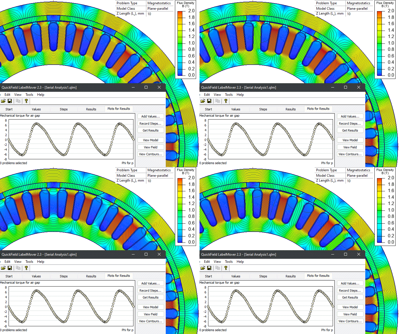
The LabelMover parametric tool is used to automatically modify the geometric model, solve and extract results, repeating this process for every straight-slot stator model.
The remaining steps are performed outside QuickField: the torque and flux linkage from each straight-slot model are summed to give the torque and flux linkage of the skewed stator; the phase flux linkage is obtained by subtracting slot flux linkages, ΨA = ΨA+ − ΨA−; the voltage is then obtained by differentiating the flux linkage-angle relationship: EMF = −dΨ/dt = −(ΔΨ/Δangle) × speed.
- Results
Cogging torque and no-load back-EMF waveforms are obtained; skewing reduces cogging torque and improves the back-EMF waveform.