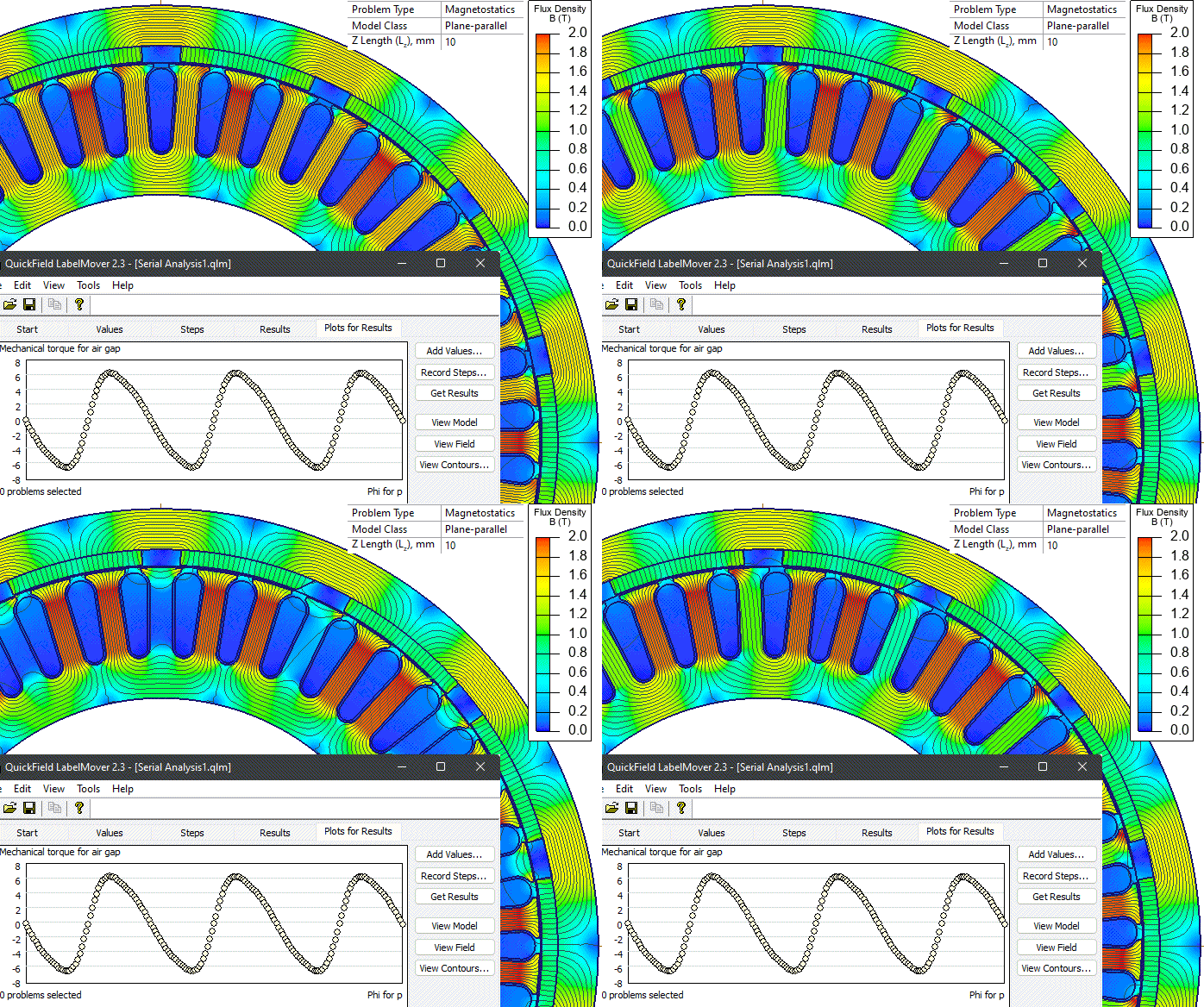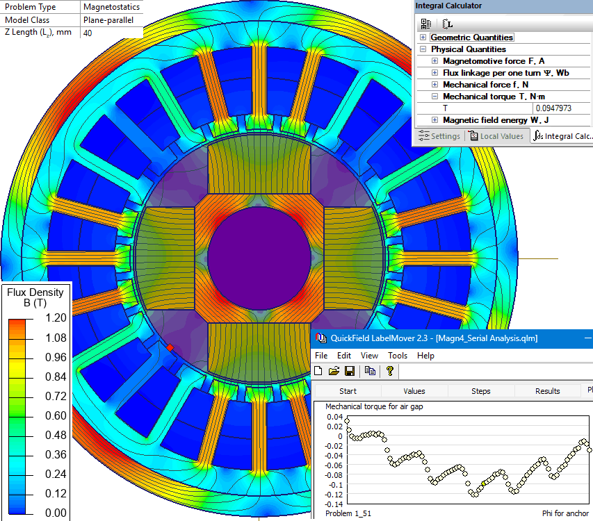
BLDC motor torque ripple
Average torque and torque ripple of a BLDC motor during electronic commutation, reflecting torque fluctuation as different stator phases are energized.
How can the average torque and torque ripple of a BLDC motor be computed without running a transient motion simulation?
Solve a series of magnetostatic problems at different rotor positions, applying the phase currents dictated by the commutation sequence at each step, measure the torque at each step and average the results.
- BLDC motor windings
- Brushless motor stator
- Permanent magnet motor phase windings
Simulation Problem
- Problem Type
- Plane-parallel DC Magnetics
- Geometry
- Motor axial length 38 mm.
- Given
- Steel permeability μ = 1000
- Permanent magnet permeability 1.05, remanence 0.4 T
- Rotor pole pairs p = 3
- Current per pole 486 ampere-turns
- Task
- Compute the average torque.
- Solution
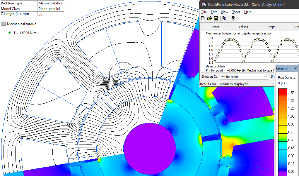
In a real motor, the control system tracks the rotor position and commutates the windings to obtain maximum torque. Here we play the role of the control system: the rotor is placed at the initial position shown in the geometric model, with phases A-B energized; after the rotor turns 20° the windings are switched to phases A-C; after another 20° the windings are switched again, and so on.
In practice there is no need to run a transient simulation with motion — it is enough to simulate a set of magnetostatic problems at discrete rotor positions with the corresponding winding currents applied.
The LabelMover parametric tool is used to generate and solve this series of problems, measuring the torque at each step.
- Results
Average torque 1.88 N·m, ranging from 1.53 to 2.04 N·m.
Reference: Motor dimensions taken from Example 9.5 in Nicola Bianchi, "Electrical Machine Analysis Using Finite Elements" (ISBN 0849333997).