Split core current transformer
Output voltage of a split-core current transformer feeding a voltmeter with finite internal resistance, computed from the given primary current and core parameters.
How can the output voltage of a split-core current transformer be found?
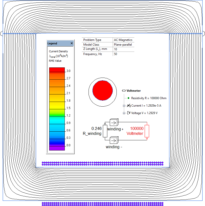
Only part of the winding is represented in the 2D geometric model; the remaining winding length is represented as an equivalent resistance in the external circuit, in series with the voltmeter's 100 kΩ input resistance.
- Split-core current transformers
- Clamp-on current sensors
- Non-invasive current measurement
Simulation Problem
- Problem Type
- Plane-parallel AC Magnetics
- Geometry
- Model z-direction length 10 mm, core 60 mm × 50 mm, with two air gaps at the joint.
- Given
- Input AC current 100 A, frequency f = 50 Hz
- Secondary winding turns N = 122, wire cross-section Sc = 0.1964 mm², copper conductivity σ = 58.5 MS/m
- Core permeability μ = 1000, with 2 air gaps of 0.1 mm each at the core joint
- Voltmeter internal resistance 100 kΩ
- Task
- Compute the transformer's output voltage.
- Solution
Only part of the winding is represented in the 2D geometric model; the missing part is represented as a resistance in the circuit.
Mean turn length 43.2 mm; the total length of the winding segments in the geometric model is 10 mm + 10 mm.
Resistance of the remaining portion: R = (1/σ) · N · (43.2 − 10 − 10) / Sc = 0.246 Ω.
- Results
Output voltage 1.3 V.