Axial flux motor back EMF
No-load back EMF in the stator windings of an axial flux motor, obtained at a given speed over a series of rotor positions.
How can a 2D model be used to compute the back EMF in the stator windings of an axial flux motor?
Slice the motor into a series of radial sections, solve each as a 2D inner-rotor model over a range of rotor positions, and derive the back EMF from the change in flux linkage.
- Axial flux motors
- Electric vehicle drive motors
- Compact permanent magnet motors
Simulation Problem
- Problem Type
- Plane-parallel DC Magnetics
- Geometry
- Stator core height 65.5 mm, tooth height 17.2 mm; rotor core height 55.6 mm, permanent magnet height 6.9 mm; diameter Ø150 mm.
- Given
- Rotor angular velocity 341.88 rad/s
- Permanent magnet coercivity Hc = 890 kA/m, remanence 1.175 T
- No-load mode, no current in the stator windings, so it can be solved as a magnetostatic problem
- Task
- Compute the back EMF in the stator windings.
- Solution
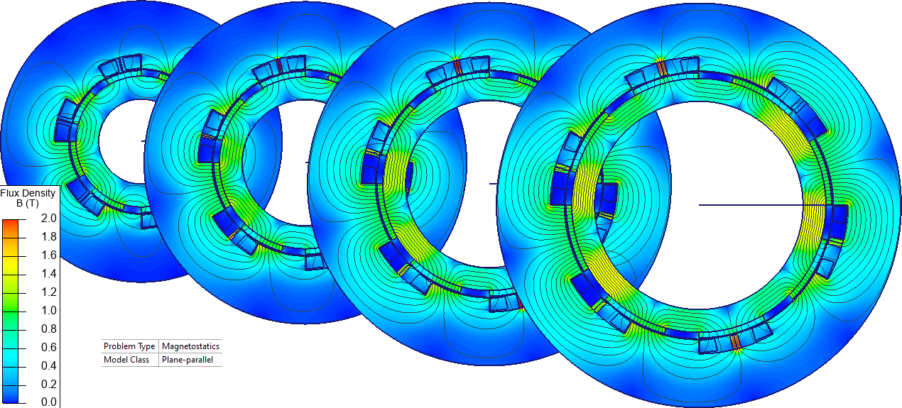
To avoid a complex 3D magnetic field analysis, the geometric model is converted into a series of 2D models. First, four circumferential slices are taken along radii r1, r2, r3 and r4, each slice representing a segment dr of the motor.
Each slice is cut open and unrolled.
The unrolled slice is then rolled into a circle with the rotor on the inside and the stator on the outside — a technique known as the “2D inner-rotor modeling method.” This converts the slice into the topology of a conventional rotating machine.
The LabelMover parametric tool rotates the rotor by 1° at a time, measuring the flux linkage with the stator windings, and the back EMF is derived from how the flux linkage varies with rotation angle.